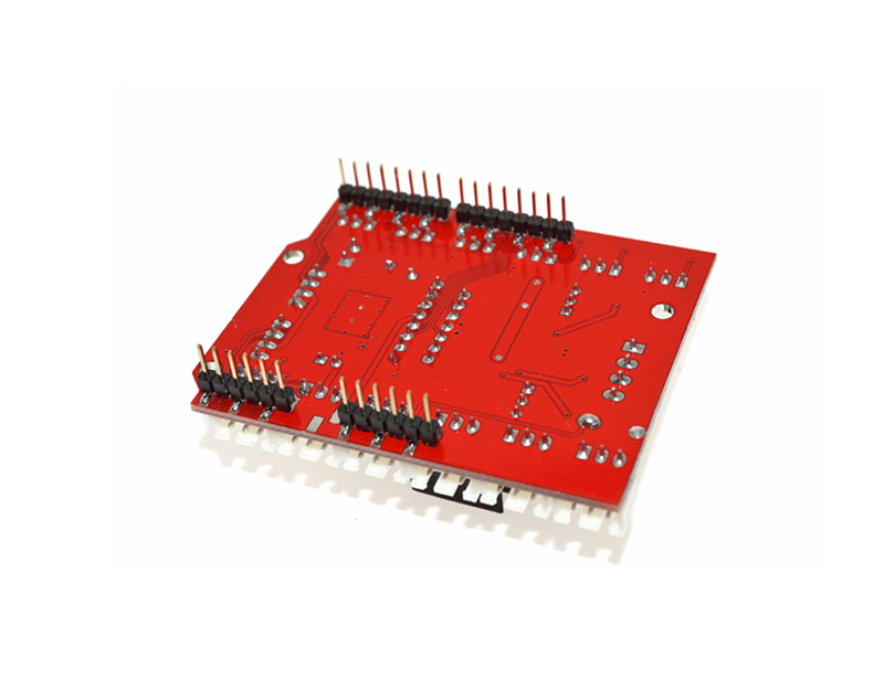

When connecting, just plug HM-10 Bluetooth module into the corresponding interface.Īt the same time, the motor drive shield has brought out extra digital and analog ports in the form of 2.54mm pin/female headers, so that you can continue to add other sensors for experiments extension. The Bluetooth interface on the motor driver shield is fully compatible with keyestudio HM-10 Bluetooth module. When connecting the motors, just plug in directly. The stackable design can make it be plugged directly into the Arduino, reducing the technical difficulty of using and driving the motor.ĭirect stack the motor driver shield onto UNO R3 board, after the BAT is powered on, turn the Slide button ON, to supply the power for both keyestudio motor driver shield V2 and UNO R3 board.įor simple wiring, the motor driver shield comes with anti-reverse PH2.0-2P connectors. We have designed the motor driver shield based on the L298P circuit. The driving current up to 2A, and output terminal of motor adopts eight high-speed Schottky diodes as protection. It can directly drive DC motors, two-phase and four-phase stepping motors. L298P is an excellent high-power motor driver IC produced by STMicroelectronics. Our robot uses the most commonly used L298P solution. The board has four LEDs to denote the direction of rotation of the motor, and the brightness level is proportional to motor speed.There are many ways to drive the motor. MA speed controlled by the Arduino's pin 9. The direction of the motor MB controlled by Arduino pins 11 and 8. MA speed controlled by the Arduino's pin 10. The direction of the motor MA controlled by Arduino pins 13 and 12. The onboard voltage regulator can not be used because motor supply voltage is too high.Įach DC motor is controlled by two pins to control the motor direction of rotation, and one pin on the PWM signal to control motor speed.

There are two ways to provide power for the motor: Vin pin through the Arduino board (switch in the VIN position) and from the VEX terminal (switch in the VEX position. In this case, the VLC switch is turned on The L298N can also use +5V logic power from the Arduino. However this voltage regulator can only be run from Voltage less than 20V., so if the motor is greater than 20V, you can not use a voltage converter circuit. To convert the motor terminal voltage VEX into useful 5V logic voltage, the motor driver board provides a voltage regulator circuit, which is activated by turning the VLO switch on. The logic voltage is 5V, usually less than the motor voltage (eg 7.2V, 9V or 12V). Motor Driver IC L298N needs two voltage: logic voltage and motor voltage. Here are the different switches available: There are different ways of getting the needed +5 V for the chip. Two different voltages are needed for the operation of this board: +5 V for the logic part and the Motor Power, which may be from 5 to 30+ volts. There is also a popular low-cost version as a module. The main changes are to add switches to more easily meet the application requirements of different motors and applied voltages.
#Keyes l298n motor driver shield drivers#
The chip contains two "H bridges" which are high-voltage and high current full-bridge drivers that can directly drive two DC motors.Īrduino L298N motor drive expansion board V03 L298N is a high voltage, high current motor driver chip, with the highest working voltage of 46V, continuous operating current of 2A, and instantaneous peak current up to 3A. 1.1 Arduino L298N motor drive expansion board V03.


 0 kommentar(er)
